Sensor Synchronization
Where This Fits
This page explains why sensor synchronization is a fundamental problem in robotics systems.
Before understanding Atlas, it is important to understand why independent sensor timing leads to inconsistent system behavior.
This is the starting point of the Atlas architecture.
From Independent Sensor Clocks → Unified Time Fabric
Modern robotics systems rely on multiple perception sensors operating simultaneously:
- cameras
- LiDAR
- IMU
- GNSS
- radar
Each of these sensors operates on its own internal clock.
For perception, localization, and SLAM pipelines to behave consistently, all sensor data must be interpreted under a common time reference.
Without this, robotics systems suffer from hidden timing errors that are difficult to detect and even harder to debug.
Atlas introduces a deterministic timing infrastructure that transforms sensor timing from an implicit problem into a controlled, observable system property.
Why Sensor Synchronization Matters
Without synchronization, timestamps drift across sensors.
This leads to:
- camera frames misaligned with LiDAR scans
- IMU readings offset from perception frames
- GNSS timestamps inconsistent with localization pipelines
These issues manifest as:
- localization drift
- unstable sensor fusion
- inconsistent replay results
- non-deterministic system behavior
In most systems, these problems are not visible directly — they appear only as downstream perception instability.
Atlas addresses this by establishing a single timing authority for the sensor domain.
What Atlas Sensor Synchronization Is
Atlas Sensor Synchronization is a system-level timing infrastructure spanning both hardware and software.
It is not:
- a trigger generator
- a timestamp utility
- a replacement for sensor drivers
Instead, it provides:
- a hardware-defined time reference
- a deterministic timing boundary
- a software time fabric for alignment and correlation
This allows all sensors — regardless of interface or capability — to participate in a shared system time model.
System Model
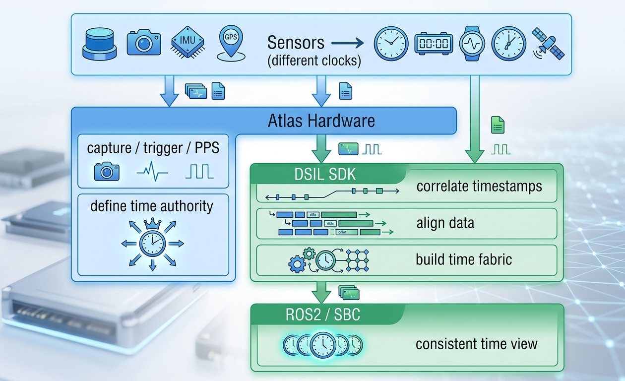
- Atlas hardware defines and distributes time
- DSIL SDK aligns and normalizes all incoming data
- Host systems (ROS2 / SBC) receive already time-consistent data
This removes the need for each sensor or driver to solve synchronization independently.
Timing Integration Reality
Not all sensors provide the same level of timing visibility or control.
In real-world systems, sensor timestamps originate from different levels of time reliability.
Levels of Time Reliability
Hardware-aligned sensors
Sensors that can directly follow external timing signals (PPS / trigger / sync)
→ Deterministic capture aligned to Atlas time authority
Signal-observable sensors
Sensors exposing timing-related signals (data-ready, sync, cadence)
→ High-confidence correlation to Atlas timing events
Transport-based sensors
Sensors where timing is only visible at data arrival (USB, Ethernet, etc.)
→ Timing must be inferred and corrected in software
Atlas is designed to work across all of these scenarios.
Instead of requiring all sensors to support hardware triggering, Atlas ensures that:
All sensors participate in a unified system time model, regardless of their native timing capability.
How Synchronization Actually Works
Atlas synchronization is completed through hardware capture + software alignment.
Step 1 — Hardware Timing Boundary
Atlas:
- ingests external or internal timing reference
- distributes PPS / SYNC / TRIGGER signals
- captures precise hardware timing events
This establishes a shared timing reference across sensors.
Step 2 — Timestamp Alignment (DSIL SDK)
The DSIL SDK builds a unified time fabric by:
- correlating timestamps across sensor data streams
- aligning all data to the Atlas time authority
- normalizing heterogeneous timing domains
What “Correction” Means
Correction does not mean modifying sensors.
Instead:
- sensors continue operating in their native timing domain
- Atlas defines the authoritative system time
- DSIL aligns each sensor’s data to that time
This is:
- system-level time alignment
- not firmware modification
- not driver replacement
This ensures compatibility with:
- UVC cameras
- LiDAR drivers
- serial sensors
- existing ROS2 pipelines
What This Achieves
With Atlas synchronization:
- hardware-triggered sensors remain fully deterministic
- non-deterministic sensors become measurable and correctable
- all sensor data becomes time-aligned and comparable
Most importantly:
Sensor timing becomes observable infrastructure, not hidden behavior
Atlas Timing Architecture
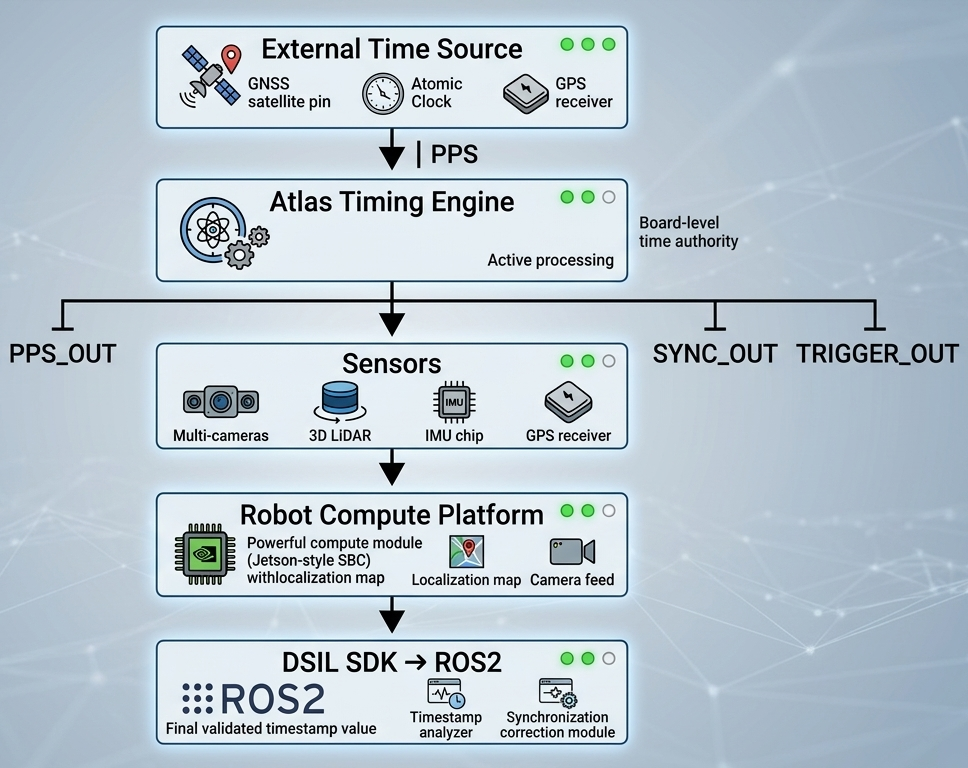
Hardware Layer (Atlas)
-
ingests timing sources (GNSS PPS, system clock, etc.)
-
distributes timing signals:
- PPS_OUT
- SYNC_OUT
- TRIGGER_OUT
-
establishes deterministic capture timing
Software Layer (DSIL SDK)
- correlates timestamps across all sensors
- aligns data into a unified time domain
- exposes timing as observable system data
Together, these layers form a complete timing infrastructure.
Hardware Timing Boundary
Atlas introduces a clear boundary:
- sensors operate in native timing domains
- Atlas captures timing events deterministically
- DSIL aligns all data before it reaches compute
This ensures that:
All downstream perception operates on consistent time
Direct-to-Compute Sensors
Some sensors bypass Atlas data path:
- Ethernet LiDAR
- GMSL cameras
- MIPI / CSI cameras
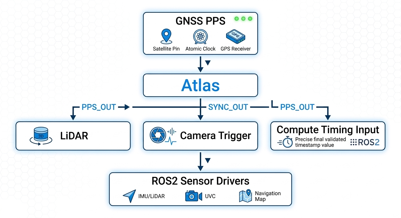
These sensors still participate in synchronization:
- capture follows Atlas timing signals or relationships
- data flows directly to compute
- DSIL aligns timestamps in software
Atlas as Time Authority
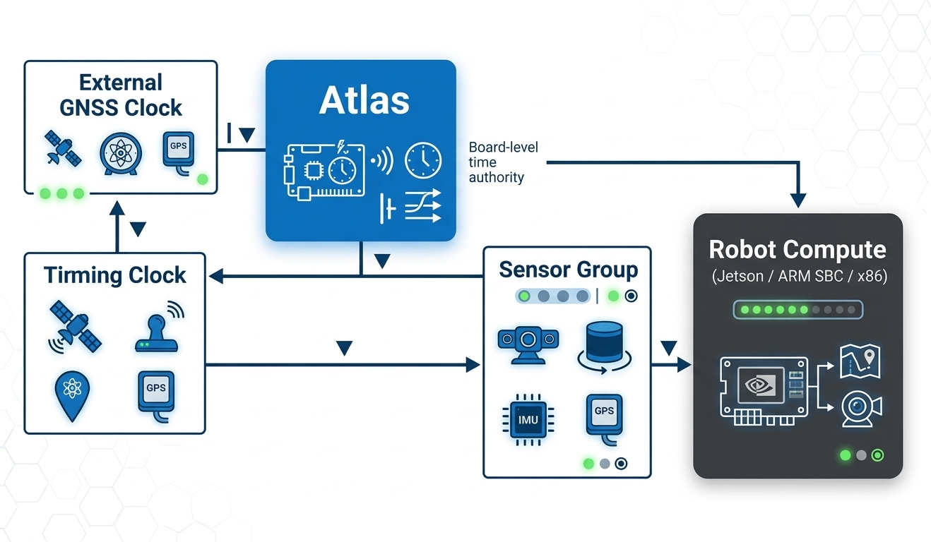
Atlas acts as the single timing reference for the perception system.
Even when sensors use different transport paths, they share:
- the same time reference
- the same alignment model
Synchronization Accuracy
| Property | Typical Value |
|---|---|
| Trigger jitter | <1 µs |
| PPS distribution skew | <1 µs |
| DSIL timestamp alignment | <1 ms |
- hardware ensures tight capture alignment
- software ensures consistent system timestamps
Timing Interfaces
| Interface | Direction | Purpose |
|---|---|---|
| PPS_IN | Input | External time reference |
| PPS_OUT | Output | PPS distribution |
| SYNC_OUT | Output | Synchronization signal |
| TRIGGER_OUT | Output | Capture trigger |
Electrical and Deployment Considerations
Atlas uses a 3.3V logic timing domain.
- do not connect directly to 5V / 12V / differential systems
- use signal conditioning for industrial interfaces
Design Guidance
- treat outputs as logic signals, not power drivers
- avoid multi-drop without buffering
- use fanout drivers for multi-sensor trigger distribution
Signal Integrity
Synchronization quality depends on:
- cable length
- shielding
- grounding
- EMI environment
Atlas guarantees timing at the board boundary.
End-to-end performance depends on system design.
Operation Modes
External Time Authority
- GNSS PPS or external clock drives system timing
Internal Time Authority
- Atlas generates timing internally
- ensures consistent operation without PPS
What This Enables
Atlas transforms synchronization into infrastructure:
- reliable multi-sensor fusion
- deterministic perception pipelines
- repeatable system behavior
- observable timing relationships
- simplified system bring-up
Summary
Atlas establishes a deterministic timing authority for multi-sensor robotics systems.
By combining:
- hardware timing distribution
- precise event capture
- DSIL-based alignment
Atlas converts sensor synchronization from:
an ad-hoc engineering problem
into:
a scalable, observable, system-level capability
What Comes Next
Now that the synchronization problem is clear, the next step is to understand how Atlas solves this at the hardware level.
Atlas establishes a physical timing boundary that enforces synchronization before data reaches the compute system.
👉 Continue to Hardware Architecture