Hardware Architecture
Where This Fits
This page describes how Atlas implements sensor synchronization at the hardware level.
After understanding the synchronization problem, this section explains how Atlas establishes a sensor domain boundary that unifies timing, power, and connectivity.
This is where the problem becomes a physical system.
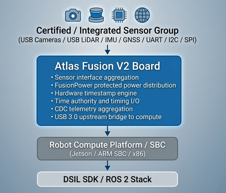
Atlas Fusion V2 provides a deterministic sensor backbone for robotics systems.
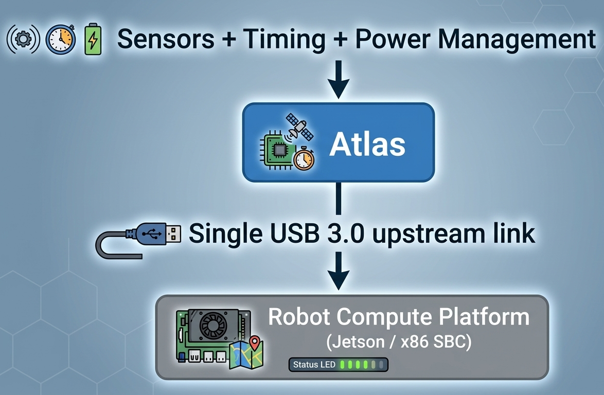
It consolidates sensor connectivity, power distribution, and timing into a single hardware layer between sensors and the robot compute platform.
What Atlas Fusion V2 Does
Atlas Fusion V2 transforms sensor integration from fragmented wiring into a structured hardware system.
Instead of connecting every sensor directly to the SBC, all sensors connect to Atlas.
Atlas exposes the entire sensor subsystem through a single upstream interface.
Core Architecture Pillars
Atlas Fusion V2 is built on three core hardware principles:
1. One-Cable Sensor Integration
Atlas replaces multi-cable sensor wiring with a single upstream connection.
Instead of:
- multiple USB cables
- separate UART wiring
- individual timing lines
- distributed power modules
Atlas provides:
- one upstream interface to the SBC
- one centralized sensor backbone
- one clean system integration boundary
Result:
- reduced cable harness complexity
- cleaner mechanical design
- lower integration effort
2. Centralized Power Distribution
Atlas provides protected onboard power for all connected sensors.
Instead of multiple external power modules, sensors are powered through a unified board-level design.
Result:
- reduced electrical noise from scattered converters
- improved power stability across sensors
- simplified system power architecture
3. Deterministic Timing Authority
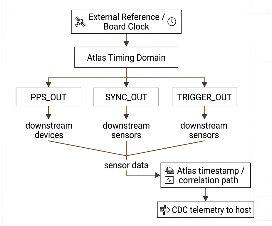
Atlas establishes a hardware-level timing boundary for all connected sensors.
It accepts external timing input and distributes synchronization signals across the sensor stack.
Result:
- aligned sensor capture timing
- consistent timestamp reference
- improved multi-sensor data correlation
Why This Architecture Matters
Traditional robotics systems connect sensors directly to the SBC, resulting in:
- 7–10 independent sensor cables routed to the SBC
- mixed interfaces across USB, UART, I2C, SPI, and PPS
- multiple sensor powers delivered through scattered converters and ad hoc wiring
- No clean timing boundary across devices
- difficult debugging and maintenance due to loose connectors and harness complexity
- Repeated engineering work for every new robot SKU
Atlas replaces this with a structured hardware model:
- one sensor backbone
- one power domain
- one timing authority
- one upstream connection
This simplifies both development and deployment.
Deployment Advantages
Simpler Integration
- fewer cables routed to the SBC
- reduced dependency on SBC I/O ports
Higher Reliability
- fewer connection points at the SBC
- reduced vibration-related failures
Cleaner Electrical Design
- centralized power reduces interference
- fewer independent switching sources
Faster Debugging
- issues can be isolated at the Atlas boundary
- no need to trace multiple cables
Platform Reuse Across SKUs
Atlas Fusion V2 is designed as a reusable sensor backbone across robot platforms.
Once adopted, the same architecture can be deployed across multiple SKUs and product lines without redesigning sensor integration.
Result:
- faster development of new robot platforms
- reduced engineering repetition
- consistent system architecture across products
System Role
Atlas Fusion V2 does not replace the robot compute platform. It manages the sensor-side infrastructure, allowing the robot compute platform to focus on: Perception,Planning and AI processing.
At the hardware level, Atlas provides:
- Sensor aggregation across mixed interfaces
- Protected onboard power for connected sensor groups
- A board-level timing authority
- External PPS input and timing signal redistribution
- Single-cable upstream integration to the compute platform
- A strong reference design for white-label OEM customization
Reference Platform for OEM Integration
Atlas Fusion V2 is designed as a production-oriented reference board, not just an evaluation kit.
It serves as a white-label hardware architecture that enables OEM teams to move from evaluation to deployment without redesigning the sensor integration layer.
How OEM Teams Use Atlas
Evaluation Reference Board
Use Atlas as-is to validate:
- sensor connectivity
- timing behavior
- system integration
Subsystem Integration Platform
Deploy Atlas as a reusable sensor subassembly in pilot or low-volume systems.
White-Label Derivative Design
Customize Atlas for production while preserving the core architecture.
Typical customization areas:
- connector configuration
- power input and budget
- timing I/O behavior
- MCU or control logic
- enclosure and branding
Summary
The Atlas hardware stack transforms sensor integration from a one-time engineering task into a scalable, reusable hardware foundation that can be deployed across multiple robot SKUs and product lines.
Hardware Specification Details
This section defines the core hardware characteristics of Atlas Fusion V2, focusing on sensor aggregation, power distribution, interface definition, and mechanical design.
Sensor Aggregation Architecture
Atlas Fusion V2 aggregates multiple sensor classes into a single board-level integration domain.
Supported sensor interfaces include:
- USB 3.0 downstream connections for cameras, LiDAR, and peripherals
- UART interface for serial sensors and telemetry devices
- I2C interface for low-speed digital sensors
- SPI interface for higher-speed peripheral communication
- Dedicated UART+PPS path for navigation or timing-aware sensors
This architecture allows the robot compute platform to interface with one unified sensor domain, instead of managing multiple independent sensor connections.
Power Distribution
Atlas Fusion V2 includes a protected onboard power system designed for robotics environments.
Input domain
- 9–24V DC input from robot battery
- reverse polarity protection
- transient and surge protection
Output domain
- 5V rail for USB sensors and high-power peripherals
- 3.3V rail for MCU and low-voltage interfaces
- No onboard 3.3V / 5V level shifting on Fusion V2; mixed-voltage support is implemented in white-label OEM PCB derivatives
Design objectives
- centralized power delivery across all sensors
- reduced reliance on external DC-DC modules
- improved electrical stability and noise control
- protection against peripheral faults
- consistent power architecture across deployments
Interface Definition
Atlas exposes a structured set of hardware interfaces for sensor integration, timing control, and host communication.
Sensor and System Interfaces
| Interface Type | Qty | Description |
|---|---|---|
| USB 3.0 Downstream | 3 | USB cameras, LiDAR, and peripherals |
| UART | 1 | Serial sensors or telemetry |
| I2C | 1 | Low-speed digital sensors |
| SPI | 1 | High-speed peripheral communication |
| UART+PPS Navigation Path | 1 | Dedicated serial path for navigation sensors |
| USB 3.0 Upstream | 1 | Connection to robot compute platform |
| DC Power Input | 1 | 9–24V system power input |
Timing Interfaces
| Interface | Role | Function in the timing system | Primary value |
|---|---|---|---|
PPS_IN | External time reference input | Receives PPS from GNSS or another high-accuracy source to align Atlas to a global or system-level reference | Gives Atlas traceable absolute time |
PPS_OUT | Standard PPS output | Redistributes a conditioned board PPS signal to downstream systems | Provides hardware heartbeat and clock reference to other devices |
SYNC_OUT | Periodic synchronization output | Emits periodic sync pulses for simultaneous sensor capture | Enables deterministic multi-sensor acquisition cadence |
TRIGGER_OUT | Programmable trigger output | Emits one-shot, burst, or scheduled trigger pulses | Precisely controls sensor action timing |
This interface model defines a clear hardware boundary between the sensor subsystem and the compute platform, while extending Atlas timing control through dedicated synchronization I/O.
Supported Sensor Categories
Atlas Fusion V2 supports multiple sensor integration models to balance plug-and-play usability, ecosystem scalability, and OEM customization.
Note: "Plug-and-play" refers to integration simplicity, not timing determinism.
The level of timing control depends on sensor hardware capabilities.
1. Descriptor-Based Integration (Certified Sensor Model)
This category includes sensors that integrate with Atlas using standard interfaces and descriptor-based integration models, without requiring Atlas-owned drivers or firmware.
Atlas does not take ownership of sensor-side software. Integration relies on:
• standard interfaces (USB UVC, CDC, UART, etc.)
• sensor vendor compliance with interface specifications
• optional validation through Atlas testing
Key characteristics
• no custom driver or firmware required from Atlas
• plug-and-play at the system integration level
• scalable without ongoing maintenance burden
• timing behavior depends on sensor capabilities (not enforced by Atlas)
Typical examples
• USB UVC cameras
• USB LiDAR devices
• standard-compliant USB or serial sensors
2. Pre-Validated Sensor Integrations (Reference Implementations)
This category includes a small set of commonly used sensors that Atlas supports with pre-validated reference implementations.
These are provided to accelerate evaluation and early-stage development.
Key characteristics
• ready-to-use integration with minimal setup
• reference firmware, configuration, or examples provided
• maintained as part of Atlas validation scope (limited set)
• plug-and-play experience, but timing determinism depends on sensor type
Typical examples
• IMU sensors (UART / SPI / I2C)
• GNSS modules with PPS support
• selected reference sensors from the Atlas evaluation kit
3. White-Label OEM Integration Sensors
This category covers sensors integrated through custom OEM or white-label designs based on the Atlas hardware architecture.
OEM teams extend Atlas to support additional sensors through hardware and software adaptation.
Key characteristics
• full flexibility for production system integration
• hardware and firmware co-design supported
• timing behavior can be optimized based on sensor capabilities
• required for proprietary or non-standard interfaces
Typical customization areas
• interface adaptation (SPI, I2C, UART, proprietary links)
• power requirements and control logic
• timing synchronization behavior
• connector types and mechanical integration
Integration Model Summary
Atlas follows a layered integration strategy:
• Descriptor-based integration for scalable, low-friction adoption
• Pre-validated sensors for fast evaluation and prototyping
• OEM customization for production deployment
This allows Atlas to function as:
• a flexible integration platform
• a deterministic timing infrastructure layer
• a production-ready hardware foundation for robotics systems
Mechanical Specification
Atlas Fusion V2 is designed for integration into mobile and industrial robotics systems.
Mechanical characteristics
- industrial-grade locking connectors for all external interfaces
- reduced risk of cable loosening under vibration
- board-level mounting holes for secure installation
- optimized connector placement for clean cable routing
Design intent
- improve mechanical reliability in field deployments
- simplify assembly and maintenance
- reduce cable strain and routing complexity
- support integration into enclosed or space-constrained systems
What Comes Next
Atlas hardware establishes timing authority, but hardware alone is not sufficient.
The next step is to understand how this timing becomes usable inside a robotics software stack.
👉 Continue to DSIL SDK